Monday, August 5, 2019

35mm Slide Copier


SLIDE COPIER

The story

I come from a large family (10 kids) and my dad (now 90 years old) liked to use his 35mm camera.
That yielded nearly 4000 slides over our childhood.
We decided that these slides needed to be captured to the cloud so we would not loose them and could share among the family.
We investigated copying services but feared the possibility of loosing them in the mail. Hey, it happened to someone in my family.
Yearning to do a build with my dad (also an engineer) we set out to make the DK^2 Slide Copier.

The best part of this project was collaborating with my dad. He in Fla and I in Utah. It was interesting for him to see the massive change in technology since he retired. He started his career with tube design and ended when MSI and micro-processors (Z80) had just hit the design stage. He wasn’t up to speed on things like the Arduino but he asked really challenging questions and was a quick study. What fun!

Design Approach

We figured handling slides was as much an art as science so rather than inventing our own feeding mechanics we decided to use a hacked slide project of the same vintage as his. We found two on ebay. I used one to gut and learn and the other as the final core of the project. It was fascinating to see how motors and mechanics were used to control this vintage machine given there were no micro-controllers available back when it was designed, but that is another story.

The Build

We built a slide copy controller using a nano which controlled relays that interfaced with the projectors slide handling buttons.

A key goal was to make minimal modifications to the slide mechanics, interfacing everything from outside the unit.

Lighting

The stock incandescent bulb was replaced with a LED Brake Light array and a diffuser plate. The collumating lenses were left intact. A socket was fabricated that is a plug replacement for the incandescent bulb. We simply removed the stock bulb and bolted in the LED array and socket. https://photos.app.goo.gl/NX8xoBfqsdbqXtTG6


Slide Photography

The final focal lens was removed and a phone was mounted at the output of the projector using a foam frame to hold it firmly to the face of the projector. The slide is illuminated down in the projector. The phone camera is adjusted to zoom up the slide to fill its screen. https://photos.app.goo.gl/nqUwEepxxEj2GfTi9

Slide Advance Control

A controlled relay is connected to the projectors remote simulating pressing the advance button. The internal voltage of the projector is low voltage AC so we decided to isolate it with relays connected across the remotes contacts. https://photos.app.goo.gl/a9jwwyJe8Hu2rTSS7

Control Panel

The controller includes switches and buttons for the operator to set tray size and copy mode as well as an OLED display to show the copiers status. 


Shutter Control

A battery operated BT selfie shutter is used to command the phone to take a photo. A relay connects the nano to the selfie module by a simple hack across its switch contacts. https://photos.app.goo.gl/87fpHH4B4Y54Vcw66


Tray & Jam Sensing

Two optical sensors were double back taped to the side of the projector. They detect tray presence and slide jams respectively. https://photos.app.goo.gl/hfbtAxzzyDPu3eiC7


Control Software

The controller software uses a simple state machine and display driver to control wait, automated copy, manual copy and diagnostics. You can select tray size and modify the starting slide #. The software detects a missing tray and slide jams.

Alignment

A transparent adapter is inserted and photographed between slide trays to indicate tray transitions and add tray descriptions. A slide target is used to adjust the camera's zoom. https://photos.app.goo.gl/2SQHhv6nkvKSZfUj8 


Performance

The copier will copy slides at a rate of 825.68 slides/hr so we expect to copy all our slides in less than 8 hrs. The projects material costs were <$100.

In Operation

Picture Quality:

We think the picture quality after a few tweaks in your photo editor will give better than original results;

Build Documentation

Schematic:


Code: 

Bill Of Material


Enjoy and Comment,
Don


Monday, January 14, 2019

Ninja Blender Spout Replacement

My Ninja Blender Spout Broke


From research on the web is seems this is a common problem. Ninja's solution is to replace the blenders entire lid. This seemed like a waste of $20 especially since I would expect this to happen again. The thin plastic tabs make this a poor design IMO.
Lets make a spout plug ....

Home Made Molding Material

Then I remembered that I could fabricate silicon parts using 1/3 corn starch and 100% silicon. "Google It" for more information.
Mix 1/3 cornstarch and the rest 100% silicon caulk. I bought mine at HD for around $3.00

Use The Top As A Mold

We are going to use the blenders top as a mold for a new spout plug by adding a top and bottom plate to the spouts cavity. Note the slot in the top plate used to relieve the silicon and make a handle for pulling the silicon plug out.
A plate is fabricated and hot glued to the underside of the spout. Note the 3 holes to relieve the silicon and air. The silicon will put in from the top of the spout and squeezed through the bottom plates relief holes. This squeeze out will be removed later. When dry this plate can be removed by prying carefully with a screwdriver. The hot glue will easily release from the plastic for cleanup.

A generous amount of the silicon mixture is put into the spouts cavity from the top and the top plate is pushed down over the silicon until it squeezes out. The stickiness of the silicon will hold the plate in place. When the silicon is dry this plate can be removed by pulling on it firmly.

The New Spout Plug

This one will never break.....

The plug after being removed from the mold and trimmed with a scissors.
Note the tab on the top used to pull the plug out.

The spout plug is pushed down into the spouts void and the tight fit holds it in place.
Pull on the tab to get it out. 

Sometimes ya just have to fix things yourself!


Enjoy and comment

Don


Sunday, November 11, 2018

Moisture Sensor


Life House

While looking for a unique and fun gift to build for my nieces wedding gift I came up with the concept of a "Lifehouse".

Concept:
It is a lighthouse turning (one of my other hobbies) that you can turn on when something pleasantly memorable happens in your life.

The build:
The lighthouse is turned linden finished in a whitewash and water based polycrylic.
The Fresnel is a 1/8" clear 3D printed cylinder.
LED's provide the light, powered by cell phone brick.
Center of tower is bored for power cable

Next:
Stay tuned for some Arduino animation in the next version :)

Pictures below are self explanatory.


Breadboarding Work Station

I do a lot of electronics bread boarding and up to now, just like most Makers, have everything flaked out on my bench. For some time I have been wanting to get things more organized making it easier to hack out my embedded controller ideas.
I wanted a work space that includes:

  • Power (5, 9, 12, 24 vdc)
  • Integrated oscilloscope and logic analyzer 
  • Control panel switches pre-wired as input and at lease one LED as output
  • A main power switch
  • Space for an Arduino


Finally, this weekend I set aside time to build my dream breadboard workstation

Oscilloscope

Although I have a nice oscilloscope I found this really impressive miniature oscilloscope that also has a 8 channel logic analyzer function.
http://www.gabotronics.com/oscilloscopes/xprotolab-plain.htm

Xprotolab Plain

I imagined that I could integrate this scope with a bread boarding station. I got one at:
http://www.amazon.com/Xprotolab-breadboard-Oscilloscope-Waveform-generator/dp/B00HWZSAPI?ie=UTF8&psc=1&redirect=true&ref_=oh_aui_detailpage_o00_s00

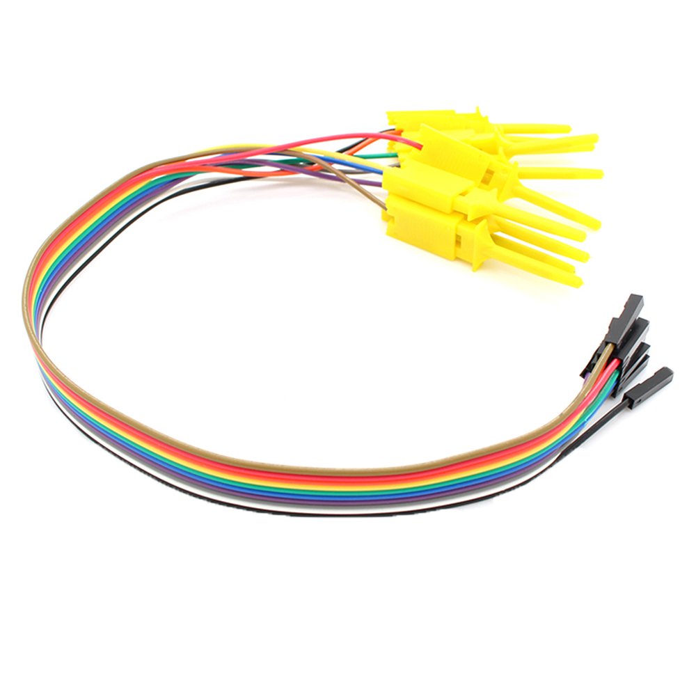
The oscilloscope is mounted to a right angle acrylic bracket with a set of probes. Well not probes rather these test clips:
http://www.amazon.com/Anycubic-Quality-Analyzer-Folder-Saleae/dp/B014PEB4ZG?ie=UTF8&psc=1&redirect=true&ref_=oh_aui_detailpage_o07_s01


The the Oscilloscope is mounted on a acrylic angle bracket that is screwed to the underside of the base. The clip wiring it restrained to that bracket. Slots were milled in the acrylic to accommodate connecting the clip wiring. The entire bracketed scope can be removed if I want to use it in another location.
This wiring schema keeps the scopes probes short and above the breadboard and out of the way.

Tablet Application

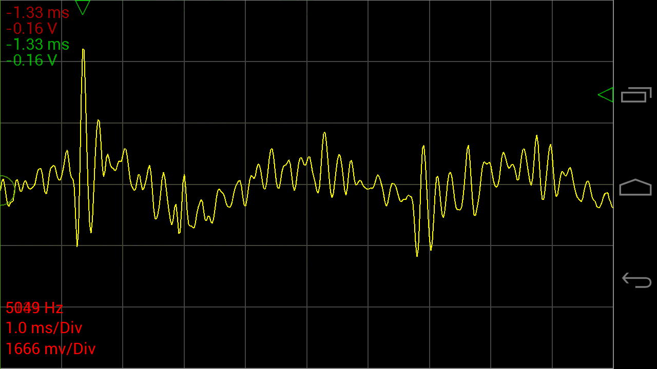
The scope connects to my tablet using this software and an OTG cable:

https://play.google.com/store/apps/details?id=com.nfx.noscpro&hl=en

   Oscilloscope Pro- screenshot

You can find a variety of OTG cables on amazon.
The tablet is held with a 2 x 4 that has a 10 degree slot cut in it to the size of the tablets thickness.

Note: I also like to use other tablet based test equipment so this setup affords me access to spectrum analysis, function generator etc.

Mechanical packaging: 

I don't have drawings for the mechanical parts because I designed them on the fly as the build evolved.
The based frame is made from some solid surface (SS) left over from the new kitchen. SS is easy to cut and it can be conveniently tapped eliminating lots of fasteners.
The control panel is fabricated from acrylic sheet (Home Depot) and bent using a shop-made hot wire acrylic bender. "Google" "Bending Acrylic" if you want to build one.

Electrical parts:

The base bread boards is made from 4 of these:
http://www.amazon.com/BB830-Solderless-Plug-BreadBoard-tie-points/dp/B0040Z4QN8?ie=UTF8&psc=1&redirect=true&ref_=oh_aui_detailpage_o00_s00

Four is probably more than I need but I like to prototype stuff and leave it set up until I have converted it to whatever the operation format is going to be, usually a one-of-a-kind soldered breadboard.

Power:

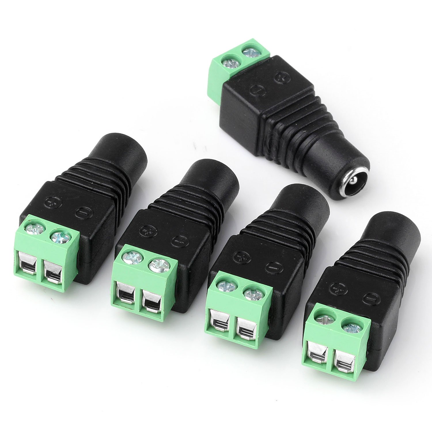
The best power setup i found is to use mini/micro USB for 5vdc and 2.1mm jacks for all other DC. All my power supplied have been fitted with these male and female jacks using these adapters:
http://www.amazon.com/JACKY-5-5mm-Female-Connector-Camera/dp/B00JMVLTA8?ie=UTF8&psc=1&redirect=true&ref_=oh_aui_detailpage_o01_s00


The 3 rear power jacks are for other voltages than 5vdc such as 9vdc, 12vdc and 24 vdc. They are wired though the main power switch and color coded wires are brought to the upper left of the breadboard for distribution.
These jacks are:  5.5mm x 2.1mm Power Jack Socket Female Panel Mount Connectors from here:
http://www.amazon.com/5-5mmx2-1mm-Power-Socket-Female-Connector/dp/B00N41C47E?ie=UTF8&psc=1&redirect=true&ref_=oh_aui_search_detailpage

The 5vdc is supplied by a micro USB connector breakout board. I like to use 5vdc bricks for my logic power. I think the breakout board came from Sparkfun.

All the power is routed through the main power switch ( a 4 pole double throw I found in my stash) for those moments when you smell smoke and want to cut all the power.

Control Panel:

I have struggled for some time with making it easy to add switches into a prototype and then I landed on simply jerking a panel from a old DVD player. This was mounted on the base, it includes 3 buttons and one LED that are wired down to the breadboard on a .1 inch connector strip.

Can't live without an Arduino:

A "biggie" Arduino is mounted on the lower left for those times when I need more compatibility or shield capability, "Arduino" style.

Final configuration


Dog Exerciser

Another ongoing project, a dog exerciser!
My dog loves to chase a laser pointer and needs regular exercise.
Built from:
-Arduino (duo)
-Custom sheild
-3d printed bracket and laser housing
-Micro servo from here: http://www.amazon.com/gp/product/B006RCLJPA/ref=wms_ohs_product_img?ie=UTF8&psc=1
-Home brew laser driver:  2N222 with laser connected in collector (+to 5v) and base connected through a 1k resistor to Arduino pin. Emitter to ground.
Laser diode with driver: http://www.adafruit.com/products/1054. Could use a laser pointer, this was easier and more rugged than taking a pointer apart and adding wires. Specs say it draws 25ma max mine measured at 15ma.
Current Features:
-Set the min and maxsweep-angle 
-Start and stop the sweep
-Laser turns on when sweep start, stops when it ends.
-Controlled from serial console, 
Next:
-BT Android app for remote control
-Pluggable BT radio so that I can use one radio and paring for many devices.
-Algorithm to adjust speed that is dependent on the angle. Insures that the linear speed is constant.
-Alarm to sound when laser starts, unit boots and on error.
-3D printed enclosure.
-Convert to a smaller Arduino like trinket
-A switch that my dog can activate
-A timer
Hint: I found that it is pretty easy to make a custom shield by taking perf board (RS) and solder pin segments just into the sections that you need for connection to the Arduino. If you do this right the board cannot- be installed wrong. I hate things that are not keyed.
As you will note this board becomes the mother board for the Arduino that plugs into it.  I leave the copper facing up and solder the parts on that side with solder bridges and wires in place of lands. I like that you can see the parts and wiring from the top making probing easy.
The only time that this is a problem is if you need all four connectors because one connector is not ion the same grid as the others (why did they do that?). In that case I cut a slot in the board with a Dremel saw and superglue the pin segment in the right place, then solder directly to the pin.

Snake Pit

I often work on display and interaction projects for our local Aquarium. This one is a simulated snake sound as a reaction to someone putting their hand in a hole in a snake put that is fabricated in the wall of an exhibit.

The project is made from:
I used the tutorials provided for the wave shield as the base code for the project and added code to convert the sensor analog value to a threshold function that will play the snake sound when the sensor is interrupted inside a preset distance.