Sunday, November 11, 2018
Life House
While looking for a unique and fun gift to build for my nieces wedding gift I came up with the concept of a "Lifehouse".
Concept:
It is a lighthouse turning (one of my other hobbies) that you can turn on when something pleasantly memorable happens in your life.
The build:
The lighthouse is turned linden finished in a whitewash and water based polycrylic.
The Fresnel is a 1/8" clear 3D printed cylinder.
LED's provide the light, powered by cell phone brick.
Center of tower is bored for power cable
Next:
Stay tuned for some Arduino animation in the next version :)
Pictures below are self explanatory.
Breadboarding Work Station

I wanted a work space that includes:
- Power (5, 9, 12, 24 vdc)
- Integrated oscilloscope and logic analyzer
- Control panel switches pre-wired as input and at lease one LED as output
- A main power switch
- Space for an Arduino
Finally, this weekend I set aside time to build my dream breadboard workstation
Oscilloscope
Although I have a nice oscilloscope I found this really impressive miniature oscilloscope that also has a 8 channel logic analyzer function.http://www.gabotronics.com/oscilloscopes/xprotolab-plain.htm

I imagined that I could integrate this scope with a bread boarding station. I got one at:
http://www.amazon.com/Xprotolab-breadboard-Oscilloscope-Waveform-generator/dp/B00HWZSAPI?ie=UTF8&psc=1&redirect=true&ref_=oh_aui_detailpage_o00_s00
The oscilloscope is mounted to a right angle acrylic bracket with a set of probes. Well not probes rather these test clips:
http://www.amazon.com/Anycubic-Quality-Analyzer-Folder-Saleae/dp/B014PEB4ZG?ie=UTF8&psc=1&redirect=true&ref_=oh_aui_detailpage_o07_s01
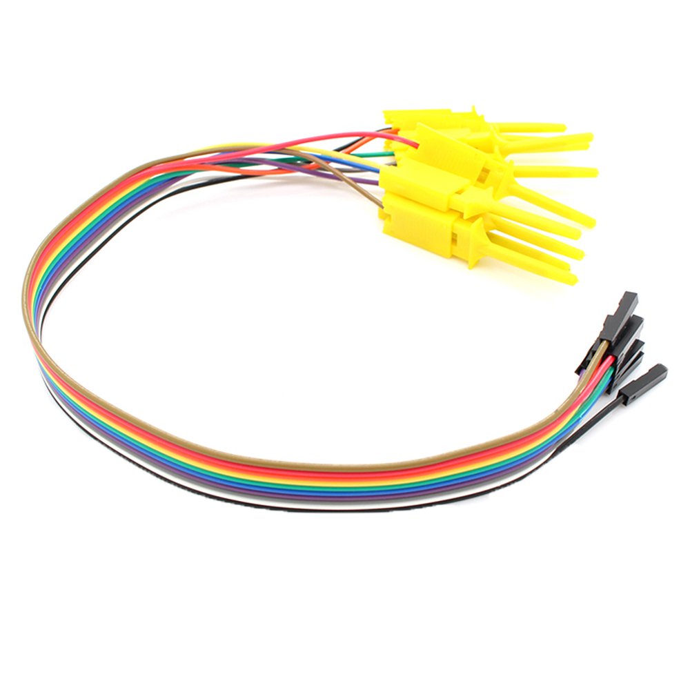
The the Oscilloscope is mounted on a acrylic angle bracket that is screwed to the underside of the base. The clip wiring it restrained to that bracket. Slots were milled in the acrylic to accommodate connecting the clip wiring. The entire bracketed scope can be removed if I want to use it in another location.
This wiring schema keeps the scopes probes short and above the breadboard and out of the way.


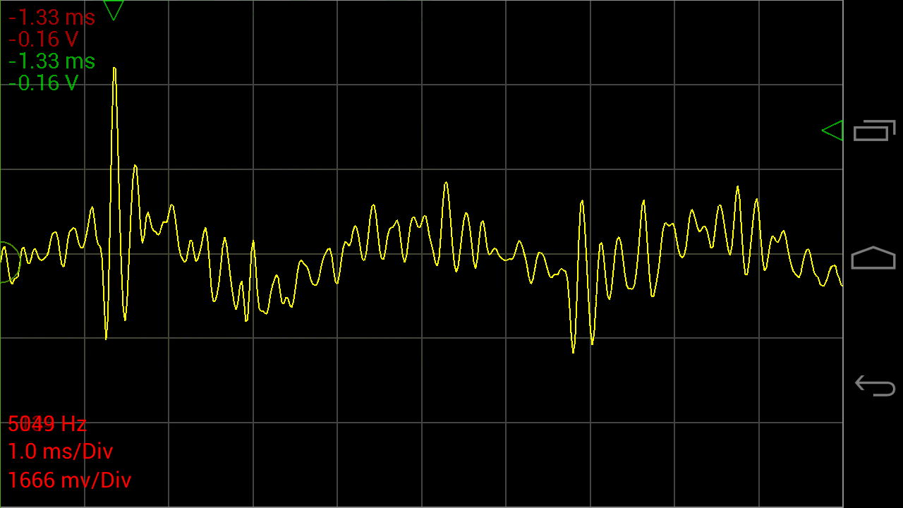
Tablet Application
The scope connects to my tablet using this software and an OTG cable:https://play.google.com/store/apps/details?id=com.nfx.noscpro&hl=en
You can find a variety of OTG cables on amazon.
The tablet is held with a 2 x 4 that has a 10 degree slot cut in it to the size of the tablets thickness.
Note: I also like to use other tablet based test equipment so this setup affords me access to spectrum analysis, function generator etc.
Mechanical packaging:
I don't have drawings for the mechanical parts because I designed them on the fly as the build evolved.The based frame is made from some solid surface (SS) left over from the new kitchen. SS is easy to cut and it can be conveniently tapped eliminating lots of fasteners.
The control panel is fabricated from acrylic sheet (Home Depot) and bent using a shop-made hot wire acrylic bender. "Google" "Bending Acrylic" if you want to build one.
Electrical parts:
The base bread boards is made from 4 of these:http://www.amazon.com/BB830-Solderless-Plug-BreadBoard-tie-points/dp/B0040Z4QN8?ie=UTF8&psc=1&redirect=true&ref_=oh_aui_detailpage_o00_s00
Four is probably more than I need but I like to prototype stuff and leave it set up until I have converted it to whatever the operation format is going to be, usually a one-of-a-kind soldered breadboard.
Power:
The best power setup i found is to use mini/micro USB for 5vdc and 2.1mm jacks for all other DC. All my power supplied have been fitted with these male and female jacks using these adapters:http://www.amazon.com/JACKY-5-5mm-Female-Connector-Camera/dp/B00JMVLTA8?ie=UTF8&psc=1&redirect=true&ref_=oh_aui_detailpage_o01_s00
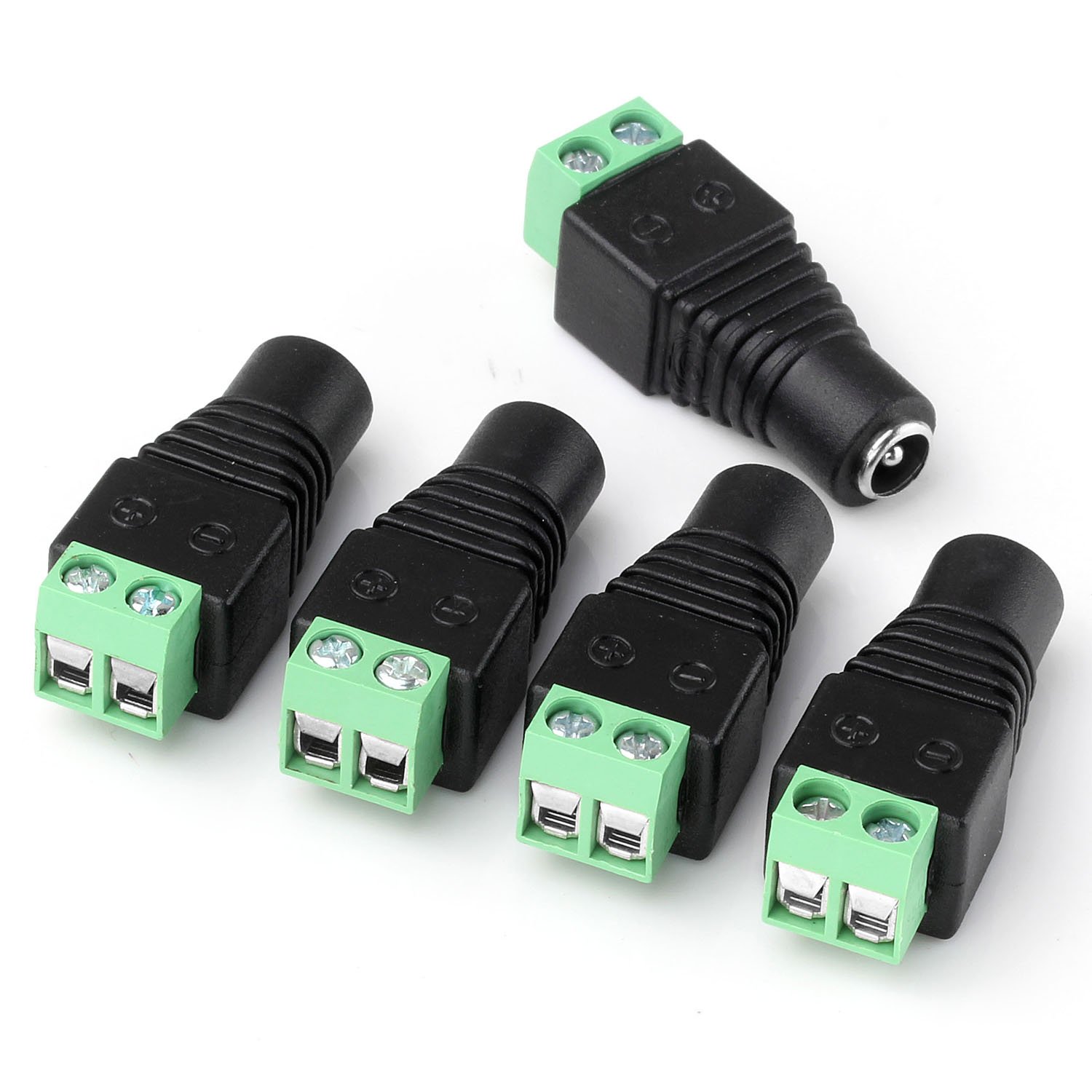
The 3 rear power jacks are for other voltages than 5vdc such as 9vdc, 12vdc and 24 vdc. They are wired though the main power switch and color coded wires are brought to the upper left of the breadboard for distribution.
 These jacks are: 5.5mm x 2.1mm Power Jack Socket Female Panel Mount Connectors from here:
http://www.amazon.com/5-5mmx2-1mm-Power-Socket-Female-Connector/dp/B00N41C47E?ie=UTF8&psc=1&redirect=true&ref_=oh_aui_search_detailpage
The 5vdc is supplied by a micro USB connector breakout board. I like to use 5vdc bricks for my logic power. I think the breakout board came from Sparkfun.
All the power is routed through the main power switch ( a 4 pole double throw I found in my stash) for those moments when you smell smoke and want to cut all the power.
 Control Panel:
I have struggled for some time with making it easy to add switches into a prototype and then I landed on simply jerking a panel from a old DVD player. This was mounted on the base, it includes 3 buttons and one LED that are wired down to the breadboard on a .1 inch connector strip.
Can't live without an Arduino:
A "biggie" Arduino is mounted on the lower left for those times when I need more compatibility or shield capability, "Arduino" style.Final configuration

Dog Exerciser
Another ongoing project, a dog exerciser!
My dog loves to chase a laser pointer and needs regular exercise.
Built from:
-Arduino (duo)
-Custom sheild
-3d printed bracket and laser housing
-Micro servo from here: http://www.amazon.com/gp/product/B006RCLJPA/ref=wms_ohs_product_img?ie=UTF8&psc=1
-Home brew laser driver: 2N222 with laser connected in collector (+to 5v) and base connected through a 1k resistor to Arduino pin. Emitter to ground.
Laser diode with driver: http://www.adafruit.com/products/1054. Could use a laser pointer, this was easier and more rugged than taking a pointer apart and adding wires. Specs say it draws 25ma max mine measured at 15ma.
Current Features:
-Set the min and maxsweep-angle
-Start and stop the sweep
-Laser turns on when sweep start, stops when it ends.
-Controlled from serial console,
Next:
-BT Android app for remote control
-Pluggable BT radio so that I can use one radio and paring for many devices.
-Algorithm to adjust speed that is dependent on the angle. Insures that the linear speed is constant.
-Alarm to sound when laser starts, unit boots and on error.
-3D printed enclosure.
-Convert to a smaller Arduino like trinket
-A switch that my dog can activate
-A timer
Hint: I found that it is pretty easy to make a custom shield by taking perf board (RS) and solder pin segments just into the sections that you need for connection to the Arduino. If you do this right the board cannot- be installed wrong. I hate things that are not keyed.
As you will note this board becomes the mother board for the Arduino that plugs into it. I leave the copper facing up and solder the parts on that side with solder bridges and wires in place of lands. I like that you can see the parts and wiring from the top making probing easy.
The only time that this is a problem is if you need all four connectors because one connector is not ion the same grid as the others (why did they do that?). In that case I cut a slot in the board with a Dremel saw and superglue the pin segment in the right place, then solder directly to the pin.

Snake Pit
I often work on display and interaction projects for our local Aquarium. This one is a simulated snake sound as a reaction to someone putting their hand in a hole in a snake put that is fabricated in the wall of an exhibit.
The project is made from:


The project is made from:
- An arduino uno
- A 3 watt stereo amplifier
- A Waveshield
- An optical sensor
- 2 speakers
- 9v power supply
Bluetooth Connected Voltmeter

Background
I started looking at a way to make a cheap power meter and realized that my Turbidity Meter project provides a nice remote voltmeter capability. So I decided to "generalize" the design and packaging.
Laser power meter
The first place I will probably use it is on the laser power meter because I can close the lid of the cutter and watch the voltage from remote. I also realized that I can log the data going to the BT app and later use it to analyze the dynamic nature of the output of the Peltier module. I am still not sure if this approach to laser power measurement will be useful and practical but I'm plowing forward until I prove it does not work.
The BT voltmeter design
Very simple it uses an Adafruit Feather 32u4 Bluefruit LE. The build information is here https://learn.adafruit.com/adafruit-feather-32u4-bluefruit-le/overview.
Some build hints are:
- The fragment of code that waits for the serial port is more important than the comments suggest, I dont think it needed just for Gemma. I had trouble with the Feather if I removed it.
- I had to disable serial communications when not connected to the PC otherwise it would hang in startup. I used A0 and when gnded it tells the controller that its connected to the USB port. I tried code-based ways to detect the serial and none worked reliable during startup. I will add this to my to-do list.
- I am running with a battery and at first it was not apparent how to turn power on and off without disconnecting the battery. You can't switch the battery as it needs to charge. Turns out just switch the En pin to gnd to turn the Feather on and off.
- When using the A/D remember that the reference voltage for the Feather is 3v so adjust the voltage calculations accordingly.
The package
The packaging needed to be modular with the LEDs on the board visible. I wanted everything mounted and wired independent of the pill-bottle. I looked for something that was laying around easy and quick, I settled on a pill bottle package.
- The Feather is hot glued to a piece of acrylic that is the width of the bottles diameter.
- The battery is glued to the bottom.
- The entire assembly is inserted into the bottle and the cap is snapped on.
- The power switch and USB connector sticks through the bottles cap and the output connector which has 4VDC, GND and Analog IN, sticks out the back.
- Two jumper pins for the "serial present" function are accessible through the side and a hole provides access to the reset button.
 |
| Everything on one substrate |

 |
| Power switch and usb port |

 |
| Jumper pins and reset hole |
Phone App
Adafruit provides a phone app that includes a BT-UART function. However I found the nRF UART v2.0 app better fit my needs. Both did the job .....

Next
I plan to use this meter to further my testing on the Laser Power meter.
Maker Don,
Bluetooth Connected Turbidity Meter
 |
| Hold handle and lower sensor into water without overflowing into the coupler |
Background
I needed turbidity values for a project I was working on so I decided to make an instrument that I could use universally.BOM
The meter consists of:
- A turbidity sensor and sensor interface board from DFROBOT. There are links on this site to more technical information. A data sheet on the turbidity sensor.
- A Feather 32U4 Bluefruit LE module.
Packaging
 |
| The sensor waterproof housing and base |
 |
| Sensor mounted to base which is glued to coupler |
 |
| Electronics acrylic covering and wiring |
 |
| The handle |
The photos shows the approach which was to house the sensor down in a waterproof cylinder that is lowered into the water. The acrylic handle houses the electronics.
- A PVC coupler is the housing.
- A circular acrylic base was cut and is glued to the bottom of the coupler with "Plumbers Goop (PG)" (my favorite glue :)).
- The base has hole drilled that fits the sensor and the sensor has an Oring fitted and then is screwed with sheet metal screws to the base. The screws are sealed with PG as well.
- The base is glued to a 90 degree acrylic bracket with acrylic cement.
- The housing is glued to the bracket with PG.
- The bracket is fitted with an acrylic cover to provide a handle and some protection for the electronics.
- The acrylic peices were bent on my "acrylic bender".
Hookup
The analog output of the turbidity sensor board is connected to the Feathers A0 analog input pin.
Power to the turbidity sensor board is provided by the VBUS power on the Feather.
Code
I used the code that Adafruit provided on the tutorial site using the blueart_cmdmode sketch.
Phone app
I used the Adafruit Bluefruit LE Connect mobile application.
Assy and test
I simply followed the Adafruit tutorial for reading analog values using the mobile app and had no problems getting a continuous reading to my phone from the turbidity sensor.Make sure that you have the switch on the sensor interface board in the analog position.
Enjoy:
Maker Don
Subscribe to:
Posts (Atom)